
The “Cold Monday” effect: thermal drift of machines and measuring instruments in SPC analysis

Introduction to the thermal stability of a process
One of the fundamental assumptions of Statistical Process Control (SPC) is the distinction between common-cause variation, which comes from the nature of the process itself, and special-cause variation, triggered by a specific, identifiable external factor. In precision metal cutting (where we work in tolerance grades IT6–IT7 or monitor critical characteristics CC/SC), the disturbances that are hardest to interpret correctly are those that do not come from a mechanical failure or human error, but from physical phenomena in the surroundings.
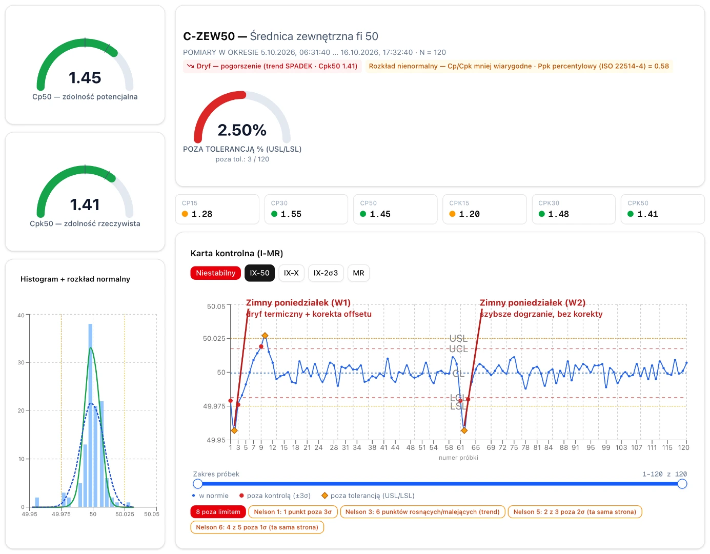
A particularly misleading measurement artefact is the so-called “cold Monday” syndrome, identified during the analysis of characteristic C-ZEW50 — outer diameter 50 mm, in the period 05.10.2026 – 16.10.2026 (N=120 measurements). It shows up as a cyclical, repeatable breakdown of process stability on I-MR control charts, only in the first hours of the morning shift after a weekend or a longer machine standstill. The control chart then records points below the lower control limit (LCL – Nelson rule 1) and a sequence of rising points (Nelson rule 3 – 6 points in a steady upward trend).
Aggregated statistics can lull the team into a false sense of security: the capability indices for the last 50 measurements suggest a stable state (Cp50=1.45 and Cpk50=1.41). A dynamic assessment of the distribution, however, points to a critical risk: the actual capability measured by the percentile index Ppk (ISO 22514-4) is only 0.58, and the line produces 2.50% of parts outside the tolerance limits (3 parts in 120 measurements).
The intuitive but wrong interpretation by those supervising production usually comes down to blaming “operators not focused after the weekend” or a delivery of raw material with different properties. The real source of the problem is the thermal expansion of metals, which affects the kinematics of the CNC machine and the elements of the measuring station alike.
The physical mechanism and the operating errors
During a two-day production standstill the machine body, spindle, ball screws, bed and cutting fluid cool down completely to the ambient temperature of the production hall, which in autumn and winter often drops to 16–18°C. Once the machine is started in the morning, its kinematic nodes begin to heat up intensively. As the temperature rises, the machine structure undergoes microscopic deformation, which directly shifts the tool zero point relative to the workpiece.
A metrological verification error makes things worse. A part taken straight from a cold machine goes to the measuring laboratory or onto an inspection plate working at the standard temperature of 20°C (in line with ISO 1). If the part is not fully acclimatised, the measurement is taken on a thermally contracted structure. As a result, a steel part with a nominal dimension of 50 mm, measured at 17°C, shows an apparent contraction of around 1.5–2 µm per 100 mm of length, which in sample 1 immediately drops the dimension below 49.95 mm (below LSL and LCL).
This is where the biggest operating trap appears: the operator over-adjusting the setup. Seeing a result below LCL/LSL in the first week (W1), the operator changes the tool offsets, moving the dimension up. Over the following hours the machine reaches thermal equilibrium (about 38–42°C at the spindle) and the coolant reaches its nominal working temperature. The dimensions of the machined parts rise naturally along a steep trend (samples 1–10 – a violation of Nelson rule 3), which, combined with the artificial morning offset correction, pushes sample 10 above the upper specification limit (USL) of 50.025 mm and produces scrap that cannot be reworked.
In the second week (W2 – sample 62) the dynamics are different: with no offset correction by the operator, the system warms up faster and naturally, and after briefly dipping towards LCL/LSL the dimensions return on their own to the centre line CL=50.000 mm, without producing scrap on the USL side. From the perspective of IATF 16949 (requirements 8.5.1.1 on control of production and 9.1.1.1 on monitoring of processes), the morning correction in W1 was a classic over-adjustment error, which led to a total of 8 points outside the decision limits of the Nelson rules (including rules 1, 3, 5 and 6).
The effect on the control chart (I-MR)
The control chart below shows an example run of the process. You can see a sharp drop in dimensions on Monday mornings, followed by a non-linear return to the stable state. Note how natural random noise makes the runs in the two weeks differ in how they return to normal, which is typical of real production environments.
Conclusions and the technical standard (preventive action plan)
Thermal drift proves that SPC charts cannot work in isolation from the physical and chemical parameters of the infrastructure (input parameters X). The fact that the averaged index Cpk50=1.41 masks a collapse in capability to Ppk=0.58 and losses of 2.50% in scrap calls for a strict operating standard:
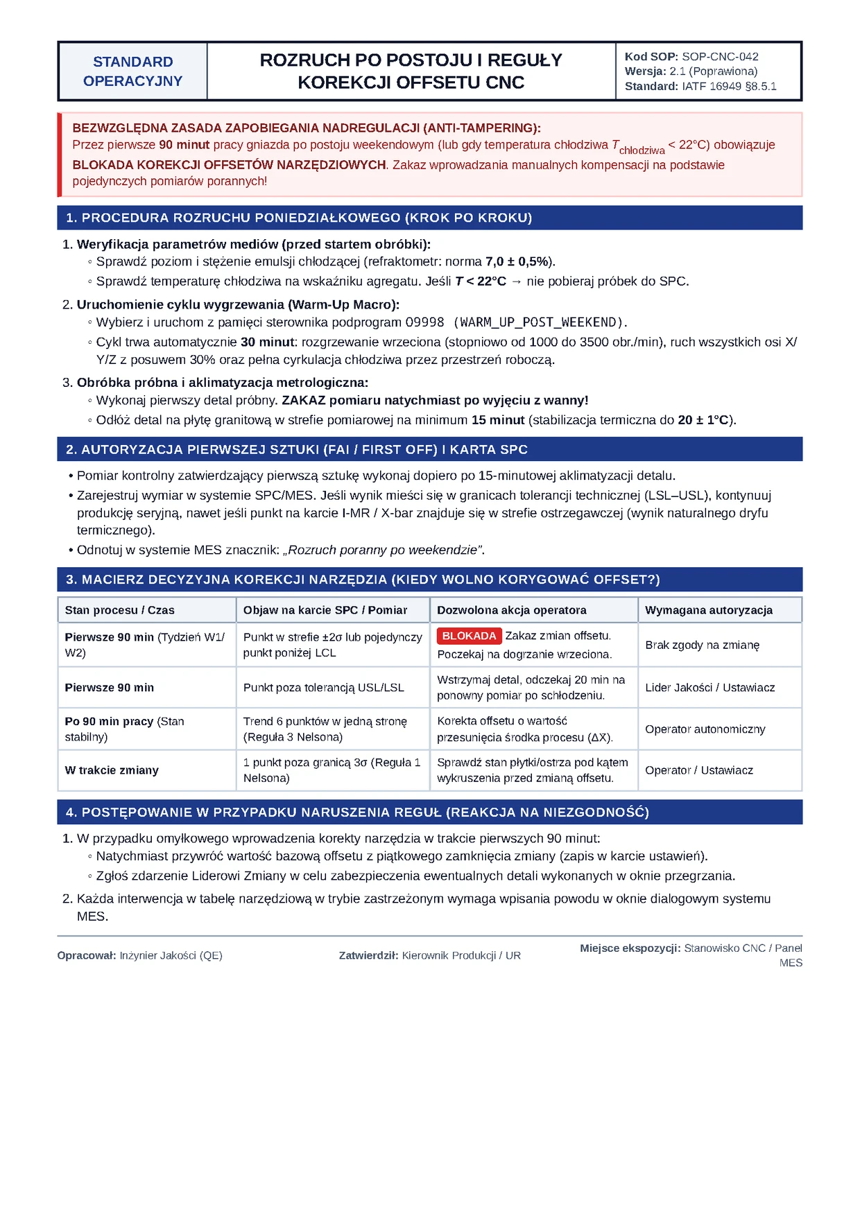
- Automated machine warm-up cycle (warm-up macro). CNC controllers should have a strictly enforced start-up program, launched automatically by the PLC schedule 30–45 minutes before the planned start of the first shift on Monday. The program must force simultaneous movement of the axes across the full working range at a limited feed, spindle rotation at 30% of rated speed and coolant circulation, which evens out the temperature gradients across the whole machine bed.
- A standard for metrological acclimatisation of parts. The First Article Inspection (FAI) procedure must include a mandatory conditioning time for the part on the granite plate of the inspection station (at least 15–20 minutes). Precision measurements must not be authorised in the MES without a reading from a pyrometer or a contact temperature sensor confirming that the part has reached 20 ± 1°C.
- Offset correction lock in the MES. Introduce a procedural rule that forbids operators from changing the offset manually on the basis of a single measurement point beyond the warning limit during the first 90 minutes of cell operation. Any correction in that window requires confirmation by a Quality Engineer or a Process Setter after the temperature parameters of the system have been verified.
Recommended way to roll the changes out to operators (SOP)
To turn this analysis into daily habits, it is worth introducing a one-page instruction at the CNC stations that governs the Monday start-up and forbids uncontrolled parameter corrections before the temperature has stabilised.
Related terms